Lab · Sep 2026
The MacArthur
A retaining wall and bridge approach on the Terminal Railroad's MacArthur crossing, built to scale inside a copy of the site.
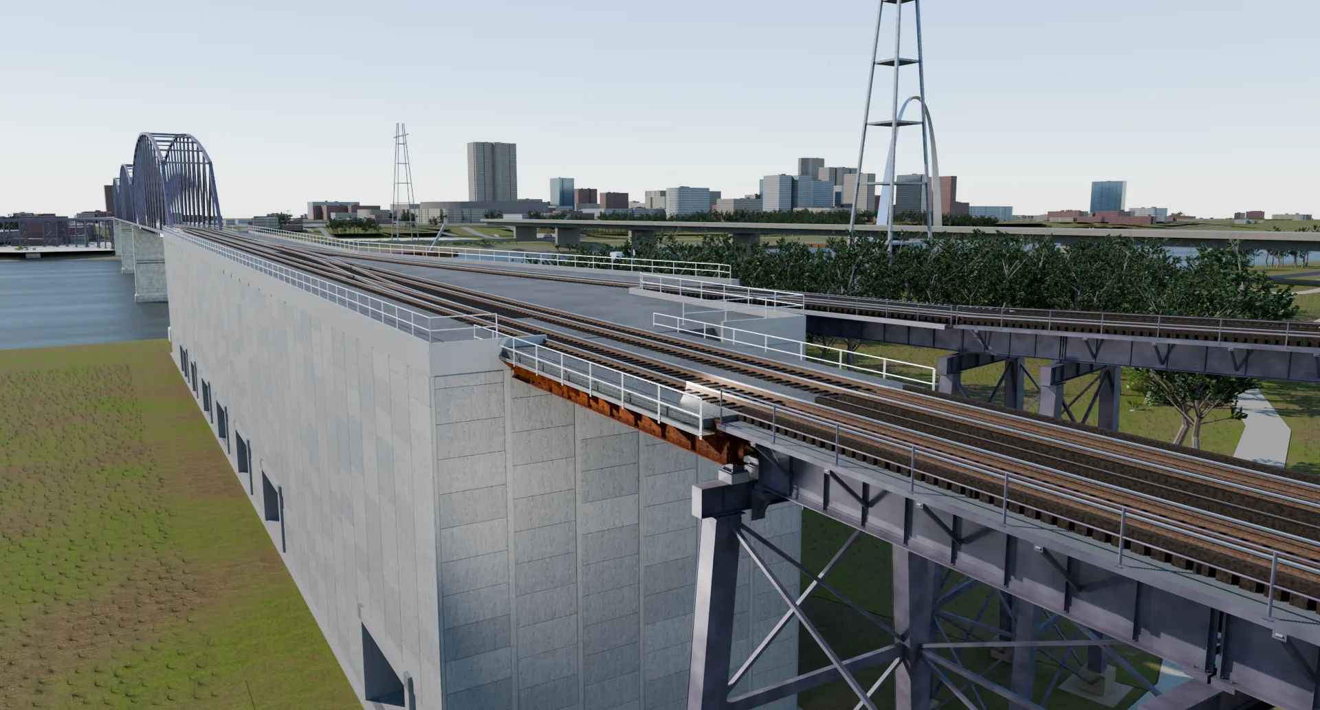
My brother had a job to price. Plans describe what gets built. They are not much use for showing someone what it is. So the site got rebuilt: the river, the floodplain, the bridge, the yard, downtown, all of it to scale, with the job standing in the middle of it.
Nothing here is invented. Alignments, roads, buildings and tree cover come from OpenStreetMap, the ground photography from the USGS National Map, which is public domain. Where the drawings and the map disagreed, the drawings won and the difference got written down.
The model
Drag to orbit. Right drag to pan. Scroll to zoom.One finger orbits. Two pan and pinch.
Loading
Six meshes, one per material system, exported from the same file the renders come out of. Isolating a system is the question anyone actually asks in front of a render. The eight thousand bolts and the rivets are left out of this copy: they are a million triangles that nobody can see at this distance. Turning the ground on brings in the rest of the scene: the terrain, downtown and the built context as real geometry, with the ground itself carrying a Cycles render of the world shot straight down, trees and all. That is another megabyte, so it is only fetched if you ask for it.
Where this is
The scene sits on a validated transform between the model and the real world. Feeding the anchors through it lands the Gateway Arch within 19 m of its published position and Busch Stadium within 8 m, which is inside the accuracy of the aerial itself. So the job can be drawn straight onto the photograph rather than pointed at.
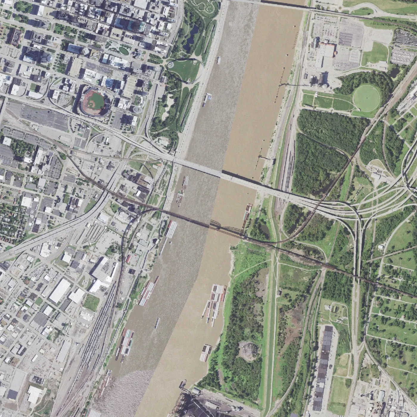
The wall
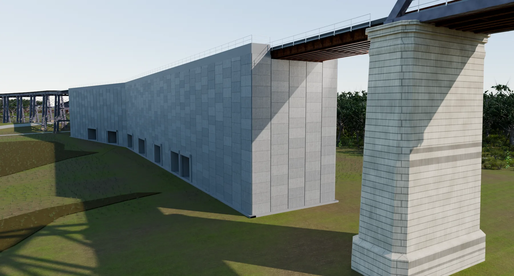
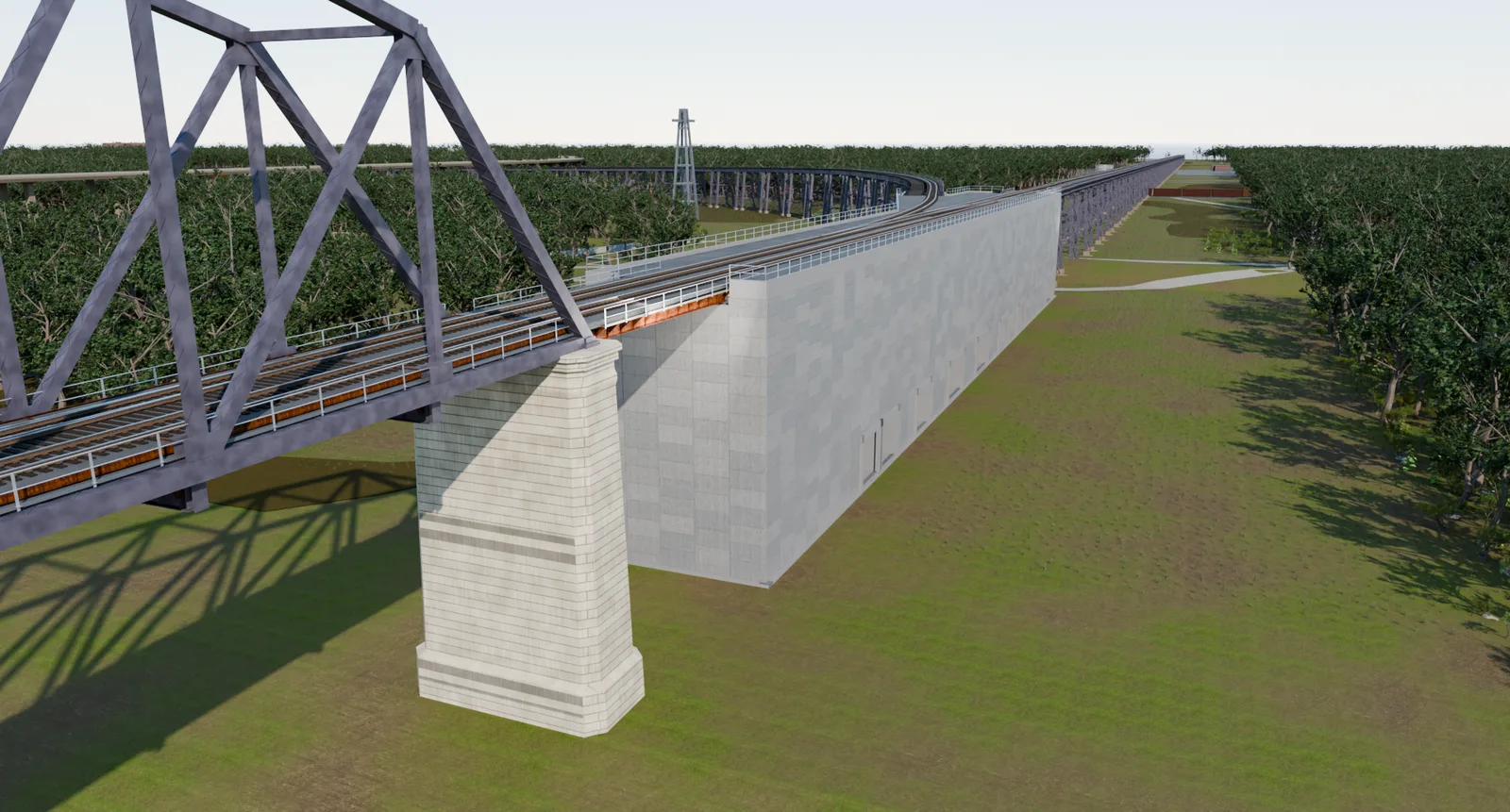
3,380 precast panels at five feet square, 19 mm joints, set 55 mm proud in running bond. Courses are level on one datum across every face. Grade trims the bottom of the stack and the coping closes the top, which is how the real thing goes up and the only way the joint lines stay straight in a render.
The bridge
The crossing started as an envelope and is now built off the sheets. The two new ballast deck spans, the truss floor, the open deck approaches and the bents under them follow the plan and steel drawings down to the bolted field splices at the third points of the girders and the bent connection plates that hang each stringer off its floorbeam. Around 8,300 bolts are modelled as bolts. Where a detail is not on a drawing it is written down as an assumption rather than quietly drawn.
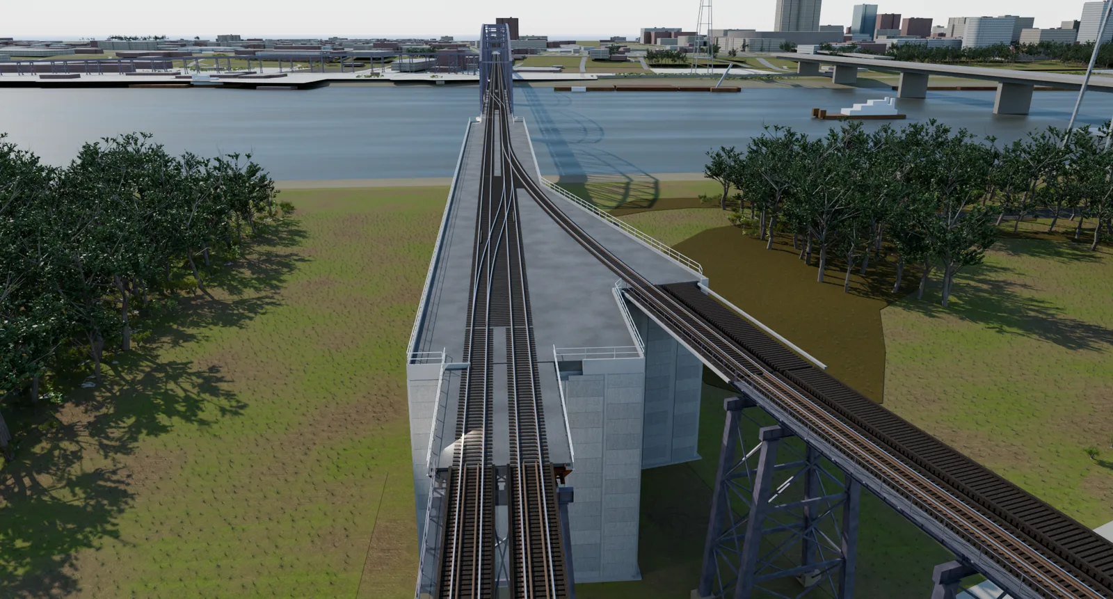
Track came with it. Both mains now run dead straight off the east truss, every turnout and crossover is a No. 12 on a 365 m curve, and the approaches carry open deck beyond the fill the way the existing structure does.

Track that would actually run
Every approach is one continuous swept mesh along a faired alignment, so stepping is impossible by construction. The joints were checked with numbers rather than eyes. Worst gap across the whole build is 5.27 mm, and the railhead never steps more than a tenth of a millimetre. Grades stay under two percent and the tightest curve is 151 m.
| Run | Length | Tightest R | Max grade |
|---|---|---|---|
| Wye, Illinois | 1,250 m | 280 m | 1.90% |
| Main east | 1,274 m | straight | 0.97% |
| West approach | 997 m | 151 m | 1.50% |
| Missouri branch | 800 m | 502 m | 1.80% |
| Illinois highway | 1,633 m | 297 m | 0.66% |
Three passes at the same frame
Ground was the whole problem. Procedural tiles cannot hold up at 800 m because a three metre tile is a few pixels. Real aerial photography on real terrain is what makes it read.
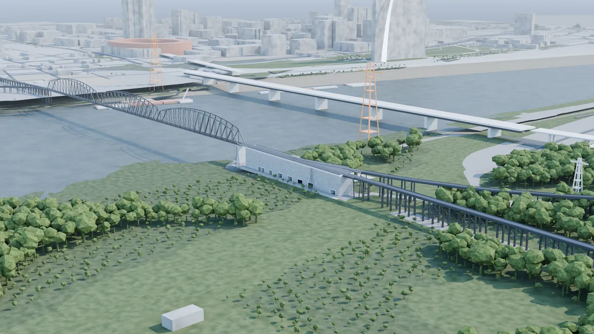 01Geometry only. Ground cover, roads and buildings pulled from the map, still flat colour.
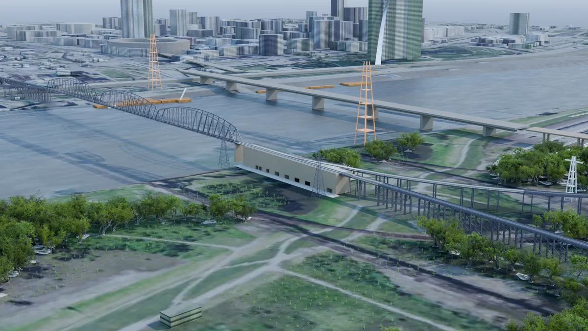 02One continuous terrain, public domain USGS aerial draped on it by world position.
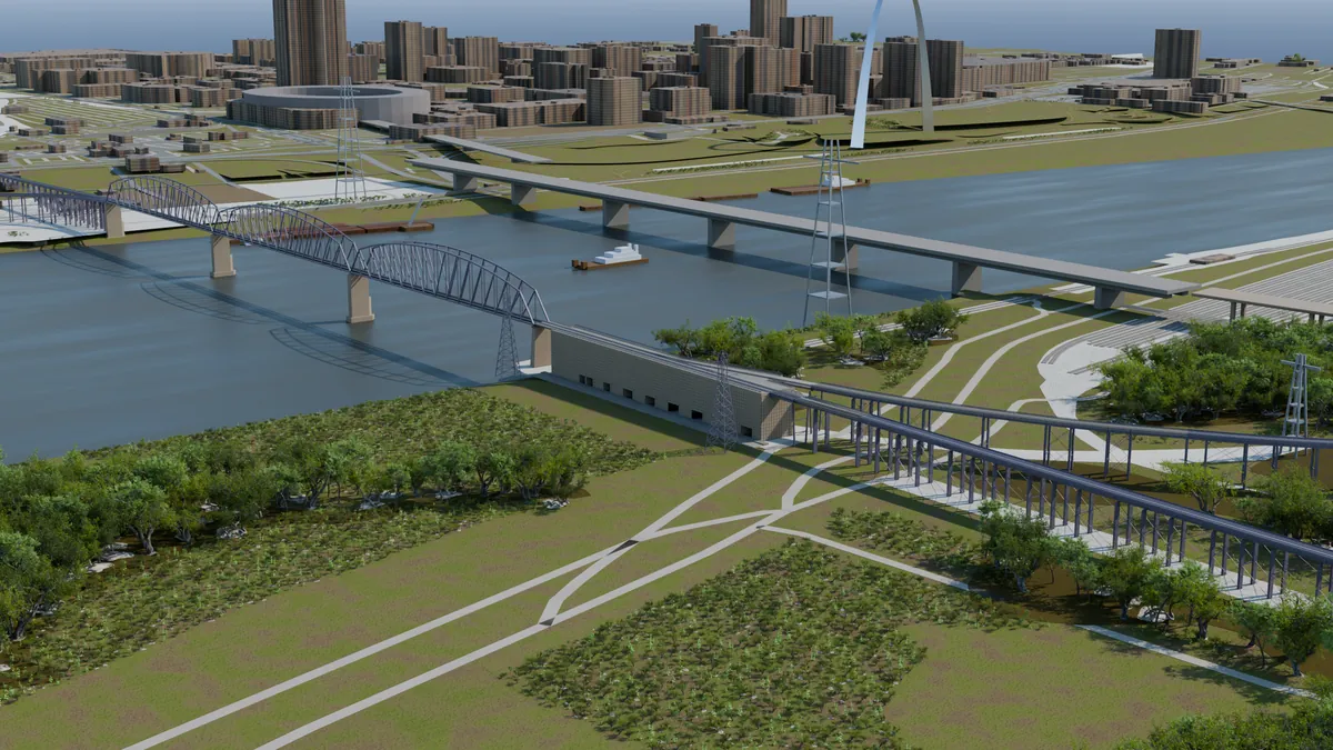 03Real vegetation, building facades, mid morning sun at 40 degrees.
What is in the scene
| Trees and scrub | 12,185, scattered inside 194 ha of mapped wood |
| Buildings | 2,629 footprints at surveyed height, tallest 192 m |
| Roads | 1,609 polylines by class, plus 44 floodplain tracks |
| Terrain | One heightfield, 12 m grid, 131k vertices |
| Aerial | 0.61 m per pixel over 5 km, 0.31 m over the job |
| Arch | The published weighted catenary. 630.0 ft, checked |
| Render | Cycles on GPU, 400 adaptive samples, 2560 by 1440 |
Still open
The wye bents are concrete columns where the original are braced lattice towers, so the styles clash at that joint. Guardrails match the envelope of the original, not its post and rail detail. The west approach is a clean arc that departs on the right tangent and lands on the right point, but wanders up to 40 m off the traced line in between. None of it is job scope. All of it is written down.